Atmospheric Ducting & Microwave Superrefraction: How Steep Refractivity Gradients and Boundary Layer Inversions Trap Radar Beams
1. Opening Scene: The Mirage in the Quiet Night
On a windless September dusk along the North Sea coastline, the transition between sea and sky dissolves into an eerie, amber twilight. As the sun drops below the salt marshes, the heat absorbed by the inland clay during the afternoon bleeds rapidly into the cloudless stratosphere. The grass crunches slightly underfoot as microscopic dew begins to condense, and a cool, heavy film of air settles over the estuary mudflats.
Standing on the shingle spit, you feel the abrupt chill pool around your ankles while your face remains enveloped in the lingering warmth of the day’s continental drift. The air smells acutely of iodine, dried kelp, and damp loam—a distinct petrichor brought on by the sudden surge in localized relative humidity. Looking out across the darkening water toward the horizon, something extraordinary occurs. Promontories, lighthouses, and offshore wind turbines that are geometrically hidden well beyond the Earth’s physical curvature begin to shimmer into view. Lights from a coastal village thirty miles away—ordinarily buried beneath the bulge of the ocean—appear suspended in mid-air, their beams steady, elongated, and unnaturally bright.
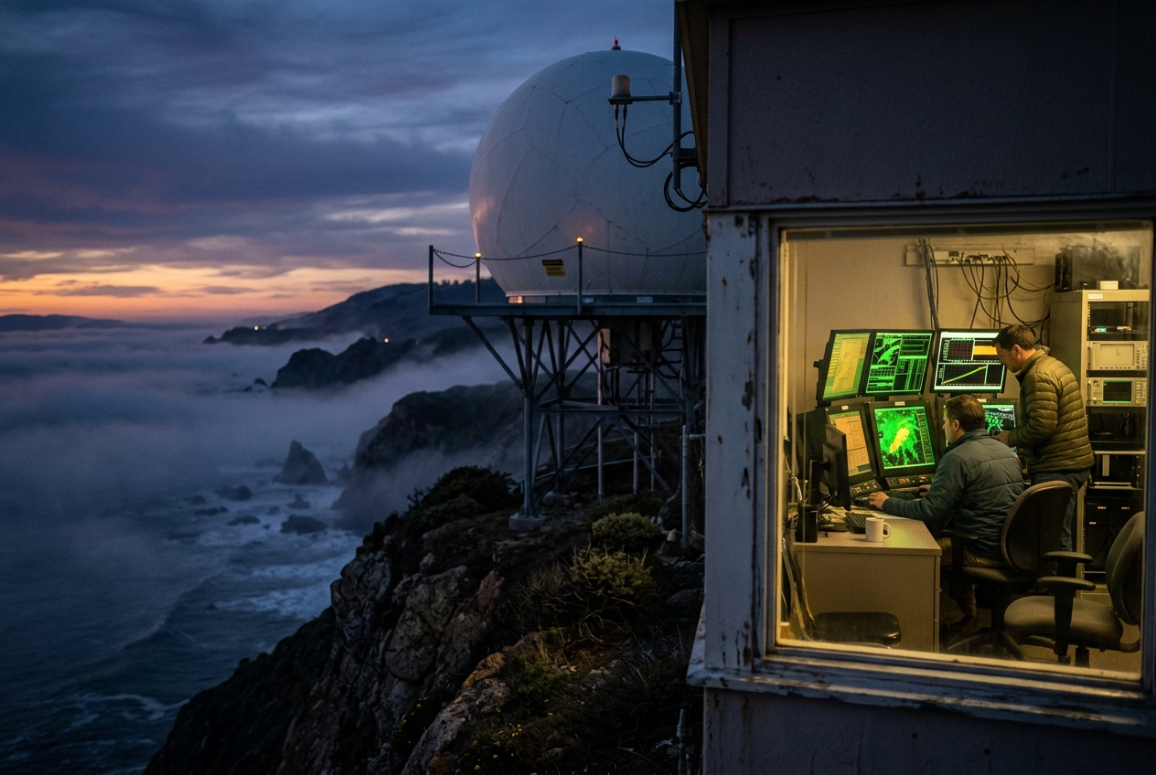
Fifty miles inland, inside the windowless operations room of a regional meteorological center, an automated alarm flashes on the workstation screen. The operational S-band Doppler radar has suddenly painted an intense, sprawling swath of stationary 65-dBZ echoes across three coastal counties—a signature that would normally signify a catastrophic supercell thunderstorm unleashing torrential rain and giant hail. Yet outside the operations building, the sky is completely clear, the stars are pin-sharp, and not a single drop of rain is falling.
The radar is not broken, nor is the observer on the coast hallucinating. Both the human eye and the multi-megawatt microwave transceiver have been ensnared by the same invisible physical phenomenon: a severe vertical gradient in the density and moisture of the lower atmosphere that has transformed the sky into an electromagnetic waveguide.
2. What’s Actually Happening: The Atmospheric Light-Pipe
To understand why radar beams and optical rays can curve around the spherical Earth, one must first discard the intuitive assumption that electromagnetic radiation always travels through the air in straight lines.
Think of the atmosphere not as a uniform, transparent void, but as an elaborate layered cake. Each slice of this cake possesses a distinct temperature, barometric pressure, and concentration of water vapor. When a wave of light or a pulse of microwave energy travels through these layers, its propagation speed changes. In warm, dry, low-density air, electromagnetic waves travel marginally faster; in cold, dense, or humid air, the waves slow down.
       WAVEFRONT BENDING DOWNWARD (SUPERREFRACTION / DUCTING)

  Faster Wave Velocity (Warm, Dry Air aloft)    --------------------->
                                               \   \   \   \   \
                                                \   \   \   \   \  (Bending Ray)
  Slower Wave Velocity (Cool, Moist Air below)   --------------------->
 ~~~~~~~~~~~~~~~~~~~~~~~~~~~~~~~~~~~~~~~~~~~~~~~~~~~~~~~~~~~~~~~~~~~~~~~~~~~
  Earth's Curved Surface (Ocean / Ground)
Consider what happens when a wheeled cart rolls diagonally across a boundary from smooth pavement into thick mud. The wheel that strikes the mud first slows down immediately, while the opposite wheel continues rolling at full speed on the pavement. The entire cart pivots, turning inexorably toward the mud.
In identical fashion, when a radar beam is launched upward at a low elevation angle into an atmosphere where warm, dry air sits directly atop a cold, moisture-laden surface layer, the upper edge of the electromagnetic wavefront travels faster than the lower edge. This velocity differential shears the wavefront, forcing the beam to bend downward toward the ground.
Under ordinary circumstances, the atmosphere naturally thins out with altitude, causing rays to bend downward just slightly—roughly matching a sphere with four-thirds the radius of the Earth. But when weather conditions produce an extreme temperature inversion (temperature increasing with height) accompanied by a rapid vertical plunge in moisture, the downward bending of the beam can actually exceed the natural curvature of the Earth itself.
When this happens, the microwave energy is trapped near the surface, bouncing repeatedly between the ground and the lower atmosphere like a laser pulse travelling through a fiber-optic cable. This phenomenon is known as atmospheric ducting or microwave superrefraction.
3. The Science: Refractivity, Waveguides, and the Mathematics of Ducting
To quantify how electromagnetic waves interact with the troposphere, atmospheric physicists use the index of refraction, $n$, defined as the ratio of the speed of light in a vacuum, $c$, to the phase velocity of the wave in the medium, $v$:
$$n = \frac{c}{v}$$
Because $n$ in the lower atmosphere is very close to unity—typically ranging between $1.000250$ and $1.000400$—working directly with $n$ introduces cumbersome decimals. Meteorologists and radar engineers therefore define the dimensionless parameter atmospheric refractivity, $N$, measured in "N-units":
$$N = (n - 1) \times 10^6$$
The Atmospheric Refractivity Equation
At radio and microwave frequencies (from roughly 100 MHz up to 40 GHz), refractivity is governed by the empirical equation formulated by Smith-Weintraub and standardized by the World Meteorological Organization (WMO) and the International Telecommunication Union (ITU):
$$N = 77.6 \frac{P}{T} + 3.73 \times 10^5 \frac{e}{T^2}$$
Where: * $P$ is the total atmospheric pressure in hectopascals ($\text{hPa}$ or $\text{mb}$). * $T$ is the absolute thermodynamic temperature in Kelvin ($\text{K}$). * $e$ is the partial pressure of water vapor in hectopascals ($\text{hPa}$).
Physical Interpretation of the Terms: 1. The "Dry" Term ($77.6 \frac{P}{T}$): Represents the electronic polarization of non-polar atmospheric molecules (predominantly molecular nitrogen, $\text{N}_2$, and oxygen, $\text{O}_2$) as their electron clouds are displaced by the passing electromagnetic field. 2. The "Wet" Term ($3.73 \times 10^5 \frac{e}{T^2}$): Represents the dipole orientation polarization of permanent water vapor molecules ($\text{H}_2\text{O}$). Because water possesses a permanent electrical dipole moment, microwave fields physically torque the molecules, an effect strongly modulated and disrupted by thermal agitation (hence the $T^2$ dependence in the denominator).
Modified Refractivity ($M$) and the Ducting Condition
As a radar beam propagates over long distances, calculations must account for the spherical geometry of the Earth. To simplify ray-tracing mathematics, physicists transform the spherical Earth into a flat surface by introducing the modified refractivity, $M$ (expressed in M-units):
$$M = N + \left( \frac{z}{a} \right) \times 10^6 \approx N + 0.157 z$$
Where: * $z$ is the altitude above mean sea level in meters ($\text{m}$). * $a$ is the mean radius of the Earth ($\approx 6,371,000\text{ m}$). * The geometric constant $\frac{10^6}{a} \approx 0.157\text{ M-units}\cdot\text{m}^{-1}$ (or $157\text{ M-units}\cdot\text{km}^{-1}$).
Differentiating $M$ with respect to altitude $z$ yields the vertical gradient of modified refractivity:
$$\frac{dM}{dz} = \frac{dN}{dz} + 0.157$$
When $\frac{dM}{dz} = 0$, the downward curvature of the ray path precisely equals the physical curvature of the Earth ($\kappa_{ray} = \kappa_{Earth} = 1/a$).
Consequently, the fundamental mathematical criterion for atmospheric trapping (ducting) is:
$$\frac{dM}{dz} < 0 \quad \iff \quad \frac{dN}{dz} < -157\text{ N-units}\cdot\text{km}^{-1}$$
If $\frac{dM}{dz} < 0$, electromagnetic rays launched at near-horizontal angles ($\theta_e < 1.0^\circ$) are bent downward with a radius of curvature smaller than the radius of the Earth, trapping the energy inside a boundary layer waveguide.
       MODIFIED REFRACTIVITY (M) PROFILES AND REFRACTIVE REGIMES

 Altitude (z)
      ^
      |     Subrefraction        Standard         Superrefraction     Trapping / Ducting
      |      (dM/dz > 157)     (dM/dz ≈ 118)     (0 < dM/dz < 118)       (dM/dz < 0)
      |          /                  /                  |                    \
      |         /                  /                   |                     \
      |        /                  /                    |                      \
      |       /                  /                     |                       \
      |      /                  /                      |                        \
      +---------------------------------------------------------------------------->
                                                                 Modified Refractivity (M)
Classification of Atmospheric Refraction Regimes
The vertical gradient of refractivity classifies the propagation of microwave signals into four distinct physical regimes:
| Refractive Regime | Refractivity Gradient ($\frac{dN}{dz}$) | Modified Gradient ($\frac{dM}{dz}$) | Physical Wave Behavior |
|---|---|---|---|
| Subrefraction | $\frac{dN}{dz} > 0\text{ N/km}$ | $\frac{dM}{dz} > 157\text{ M/km}$ | Beam bends away from Earth; overshoots targets; reduces radar horizon. |
| Standard Refraction | $\approx -39\text{ N/km}$ | $\approx +118\text{ M/km}$ | Classical $4/3$ effective Earth radius model; standard geometric propagation. |
| Superrefraction | $-157 < \frac{dN}{dz} < -39\text{ N/km}$ | $0 < \frac{dM}{dz} < 118\text{ M/km}$ | Beam bends downward toward Earth more than standard; extends radar horizon. |
| Trapping / Ducting | $\frac{dN}{dz} < -157\text{ N/km}$ | $\frac{dM}{dz} < 0\text{ M/km}$ | Beam trapped in atmospheric waveguide; creates extreme ground clutter & blind zones. |
Worked Physical Example: The Genesis of a Nocturnal Duct
Let us calculate the refractivity profile for a realistic radiation inversion over damp soil to determine whether a surface duct forms.
1. Ground Level Conditions ($z_0 = 0\text{ m}$):
- Surface Pressure: $P_0 = 1013.25\text{ hPa}$
- Surface Temperature: $T_0 = 283.15\text{ K}$ ($10.0^\circ\text{C}$)
- Saturated Vapor Pressure ($RH = 100\%$): $e_0 = 12.28\text{ hPa}$
Calculating $N_0$: $$N_0 = 77.6 \left( \frac{1013.25}{283.15} \right) + 3.73 \times 10^5 \left( \frac{12.28}{(283.15)^2} \right)$$ $$N_0 = 77.6(3.5785) + 3.73 \times 10^5 (0.00015317) = 277.69 + 57.13 = 334.82\text{ N-units}$$ $$M_0 = N_0 + 0.157(0) = 334.82\text{ M-units}$$
2. Inversion Top Conditions ($z_1 = 150\text{ m} = 0.15\text{ km}$):
Radiational cooling has chilled the ground, while warm, dry advection sits aloft: * Pressure at $150\text{ m}$: $P_1 = 995.50\text{ hPa}$ * Temperature at $150\text{ m}$: $T_1 = 293.15\text{ K}$ ($20.0^\circ\text{C}$, a $+10\text{ K}$ temperature inversion) * Vapor pressure drops sharply to dry air ($RH = 30\%$ at $20^\circ\text{C}$): $e_1 = 7.02\text{ hPa}$
Calculating $N_1$: $$N_1 = 77.6 \left( \frac{995.50}{293.15} \right) + 3.73 \times 10^5 \left( \frac{7.02}{(293.15)^2} \right)$$ $$N_1 = 77.6(3.3959) + 3.73 \times 10^5 (0.00008169) = 263.52 + 30.47 = 293.99\text{ N-units}$$
Now calculate $M_1$: $$M_1 = N_1 + 0.157(150) = 293.99 + 23.55 = 317.54\text{ M-units}$$
3. Refractivity Gradient Calculation:
$$\frac{dN}{dz} = \frac{N_1 - N_0}{z_1 - z_0} = \frac{293.99 - 334.82}{0.15\text{ km}} = \frac{-40.83}{0.15} = -272.2\text{ N-units}\cdot\text{km}^{-1}$$ $$\frac{dM}{dz} = \frac{M_1 - M_0}{z_1 - z_0} = \frac{317.54 - 334.82}{0.15\text{ km}} = \frac{-17.28}{0.15} = -115.2\text{ M-units}\cdot\text{km}^{-1}$$
Key Result: Because $\frac{dN}{dz} = -272.2\text{ N/km} < -157\text{ N/km}$ (and correspondingly $\frac{dM}{dz} = -115.2\text{ M/km} < 0$), this atmospheric boundary layer satisfies the critical condition for trapping/ducting. Any radar beam entering this layer at an angle shallower than approximately $0.8^\circ$ will be trapped entirely within the surface-based duct.
4. Meteorological Architecture: Synoptic & Mesoscale Setups
Atmospheric ducts are not random anomalies; they are direct signatures of specific synoptic and mesoscale configurations. Three primary meteorological mechanisms drive their formation:
                          THREE CLASSICAL DUCTING ARCHITECTURES

 1. NOCTURNAL RADIATION DUCT      2. MARINE ADVECTION DUCT         3. SUBSIDENCE INVERSION DUCT

   Warm, Dry Air Aloft             Hot, Dry Continental Air         Warm, Dry Sinking Air (Hadley)
  --------------------------     --------------------------       ================================ Inversion Base
   Radiative Cooling Inversion    Marine Boundary Layer (Moist)    Cool, Humid Marine Stratocumulus
  ~~~~~~~~~~~~~~~~~~~~~~~~~~     ~~~~~~~~~~~~~~~~~~~~~~~~~~       ~~~~~~~~~~~~~~~~~~~~~~~~~~~~~~~~
     Cold Ground at Night                Cold Ocean Surface              Ocean Surface (Trade Winds)
1. Nocturnal Radiation Inversions (Surface Ducts)
Under clear skies and light synoptic winds associated with high-pressure systems, terrestrial longwave radiation escapes freely to space. The ground cools rapidly, chilling the adjacent air layer while air several hundred meters above retains daytime heat. If the surface is damp (e.g., irrigated fields or river valleys), strong moisture pooling occurs at the base while the air above remains dry. This generates a steep negative lapse rate of both temperature and vapor pressure, yielding surface ducts between $50\text{ m}$ and $300\text{ m}$ thick.
2. Warm Continental Advection over Cold Seas (Elevated & Surface Ducts)
When a warm, dry continental air mass is transported offshore across a colder sea or lake surface, sensible heat fluxes chill the lowest air layers from below, establishing a stable marine boundary layer capped by dry continental air. This process is extensively documented by organizations like the National Oceanic and Atmospheric Administration (NOAA) and the UK Met Office. It frequently triggers intense superrefraction across coastal waters, such as the Persian Gulf, the Mediterranean Basin, the Baltic Sea, and the California Current.
3. Large-Scale Subsidence Inversions (Elevated Ducts)
Within the descending branches of Hadley cells (such as subtropical oceanic anticyclones) and beneath strong synoptic high-pressure ridges, adiabatic compression warms and dries the sinking air aloft. This dry, warm air caps the cool, moisture-saturated marine boundary layer below, forming elevated ducts between $500\text{ m}$ and $2,500\text{ m}$ altitude. These persistent waveguides span thousands of square kilometers across the trade wind belts.
4. Oceanic Evaporation Ducts
Over open oceans, the continuous transition from 100% relative humidity at the air-sea interface to ambient maritime humidity above creates a ubiquitous, semi-permanent shallow duct. This evaporation duct is typically only $5\text{ m}$ to $30\text{ m}$ deep, but it dictates the operational range of shipborne navigation radars and marine communications. For further reference on maritime propagation, see the American Meteorological Society (AMS) Glossary and the Wikipedia: Atmospheric Ducting treatise.
5. Operational Impacts on Radar Meteorology and Remote Sensing
When an atmospheric duct captures a radar beam, standard beam-propagation algorithms fail, producing severe operational errors in operational weather forecasting and radar product interpretation.
       STANDARD PROPAGATION VERSUS DUCTING BEAM PATHS

 Height
   ^                                     Target Storm Core (Missed in Ducting)
   |                                         [ *** Rain *** ]
   |                                             [ ***** ]
   |                        Standard Ray Path   /
   |                           (4/3 Earth)    /
   |                                        /
   |                                      /
   |                                    /    Trapped Ray Path (Ducting)
   |   Radar                         /  . - - - - - - - - - - - - - - - - .
   |  [|/|]========================' . '                                    \
   |  / | \                      . '                                         \ Ground Clutter
   +--------------------------------------------------------------------------\----------> Range
                                                                             /// Hills ///
1. Anomalous Propagation (AP) Ground Clutter and False Precipitation
When a radar beam is bent downward into terrain, hills, buildings, or ocean waves, the backscattered power produces high-reflectivity echoes known as Anomalous Propagation (AP). Because modern radar algorithms relate equivalent radar reflectivity factor ($Z$) to rainfall rate ($R$) via power-law relations such as the Marshall-Palmer formula:
$$Z = a R^b \quad (\text{e.g., } Z = 200 R^{1.6})$$
A ground bounce producing a false return of $55\text{ dBZ}$ is misinterpreted by automated systems as extreme, torrential rainfall exceeding $100\text{ mm/hr}$ ($4\text{ in/hr}$). This can corrupt flash-flood guidance models and trigger false civil protection alerts.
2. Radar Shadow Zones and Beam Blockage
When the lowest elevation angles are trapped within a surface duct, electromagnetic energy cannot escape to higher tropospheric altitudes. This creates a severe radar shadow zone above the duct. Convective cells, multi-cell updrafts, and severe hailstorms developing in this shadow zone remain entirely invisible to the radar until they grow tall enough to penetrate the higher, unbent elevation scans.
3. Overshooting Precipitation Cores
Conversely, if an elevated duct intercepts a beam and refracts it away from its expected trajectory, or if standard $4/3$-Earth propagation assumptions fail, the radar beam can overshoot shallow low-level winter snowstorms or under-sample low-altitude rotation signatures (mesocyclones and tornado vortex signatures) in severe supercells, as detailed by research at the National Severe Storms Laboratory (NSSL).
4. Dual-Polarization Hydrometeor Classification Errors
Modern dual-polarization weather radars transmit and receive both horizontally ($H$) and vertically ($V$) polarized pulses. Meteorologists rely on dual-polarization variables: * Differential Reflectivity ($Z_{DR} = 10 \log_{10} \frac{Z_H}{Z_V}$): Measures hydrometeor oblate shape. * Copolar Correlation Coefficient ($\rho_{HV}$): Measures hydrometeor diversity within the pulse volume. * Specific Differential Phase ($K_{DP}$): Measures liquid water content independent of attenuation.
During ducting events, side-lobe and main-lobe contact with ground targets causes $\rho_{HV}$ to collapse from typical meteorological values ($\rho_{HV} > 0.96$ for rain and hail) to non-meteorological values ($\rho_{HV} < 0.70$). Uncompensated AP returns corrupt fuzzy-logic Hydrometeor Classification Algorithms (HCA), causing ground clutter to be misclassified as giant hail, biological scatterers (birds/insects), or tornadic debris.
6. Advanced Signal Processing and NWP Mitigation Strategies
To maintain data integrity in modern numerical weather prediction (NWP) and aviation hazard systems, radar engineers employ three layers of signal-processing defense:
               RADAR DATA PURIFICATION PIPELINE UNDER DUCTING

 +--------------------+      +--------------------+      +--------------------+
 |  Raw IQ Signal     | ---> | Doppler Filtering  | ---> | Dual-Pol Texture   |
 |  Time Series Data  |      | Zero-Velocity Notch|      | Spatial Coherence  |
 +--------------------+      +--------------------+      +--------------------+
                                                                    |
                                                                    v
 +--------------------+      +--------------------+      +--------------------+
 | NWP 4D-Var Data    | <--- | Real-Time Ray      | <--- | Clutter Phase Map  |
 | Assimilation Model |      | Tracing Correction |      | Refractivity Index |
 +--------------------+      +--------------------+      +--------------------+
1. Doppler Spectral Filtering and Zero-Velocity Notching
Because terrain, mountains, and man-made structures are stationary, the Doppler spectrum of AP clutter is centered sharply at zero radial velocity ($v_r = 0\text{ m/s}$). Advanced radar signal processors employ infinite impulse response (IIR) or finite impulse response (FIR) high-pass notch filters to suppress power within $\pm 0.5\text{ m/s}$ of zero velocity, attenuating stationary clutter by $50\text{ dB}$ to $70\text{ dB}$.
However, when wind blows through trees, or when the ocean surface moves in swell waves, the clutter develops a non-zero spectral width that can bypass simple notch filters, requiring advanced Gaussian Transform clutter estimators.
2. Dual-Polarization Texture and Spatial Despeckling
Meteorologists apply texture algorithms that evaluate the local standard deviation of differential phase ($\sigma_{\Phi_{DP}}$) and correlation coefficient ($\rho_{HV}$). Non-meteorological AP clutter exhibits high spatial variance in $\Phi_{DP}$ alongside erratic $Z_{DR}$ swings. Automated masks flag and eliminate these contaminated range bins prior to generating quantitative precipitation estimates (QPE).
3. Radar-Derived Refractivity Mapping ($N$-Metering)
Remarkably, anomalous propagation can be converted from an operational nuisance into a meteorological measurement tool. By tracking the ultra-stable phase shift ($\Delta \phi$) of radar echoes returning from known, stationary ground targets (such as telecommunication towers and radio masts), meteorologists can calculate changes in refractive index along the path:
$$\Delta \phi(r) = -\frac{4\pi f}{c} \int_0^r \Delta n(s) \, ds = -\frac{4\pi f}{10^6 c} \int_0^r \Delta N(s) \, ds$$
This technique, pioneeringly developed by Fabry and operationalized by research centers, maps high-resolution surface moisture fields in real time. These derived moisture profiles are assimilated directly into convective-scale Numerical Weather Prediction (NWP) systems via 4D-Var schemes, helping forecast convective initiation hours before thunderstorms erupt.
7. Practical Outdoor Guidance: Observing the Invisible Duct
While radar operators grapple with false echoes, outdoor observers can directly spot, measure, and leverage atmospheric ducting with basic tools and careful observation.
                  THE OBSERVER'S DUCTING CHECKLIST

 [1] THE SKY: Clear, cloudless sunset; sharp haze layer or boundary-layer smog cap.
 [2] THE HORIZON: "Looming" mirages; distant towers visible beyond normal curve.
 [3] INSTRUMENTS: Rapid drop in evening temperature + sharp rise in barometric pressure.
 [4] RADIO DX: Distant FM stations / VHF channels overwhelming local broadcasts.
What to Look for in the Sky and on the Horizon
- Looming and Superior Mirages: When walking along a coastline or wide plain at dusk under clear skies, watch for distant landmarks (ships, islands, hills) that appear elevated, vertically stretched, or visible when they should be geometrically beneath the horizon.
- Sharp Haze Discontinuities: Look for a razor-sharp horizontal boundary capping ground haze or smoke. This line marks the base of the temperature inversion and the upper boundary of a potential duct.
- Green Flash Phenomenon: Under strong superrefractive marine inversions, optical refraction separates the solar spectrum at sunset, amplifying the duration of the green flash.
Instrument Readings to Monitor
- Barometer: Look for a steady, high barometric reading ($> 1020\text{ hPa}$) associated with synoptic anticyclones and calm conditions.
- Thermometer and Psychrometer: Measure temperature and relative humidity at two heights (e.g., ground level vs. $2\text{ m}$ up). A strong ground chill combined with rapid saturation at the surface indicates a developing radiation inversion.
- Wind Vane / Anemometer: Look for calm surface winds ($< 3\text{ knots}$) accompanied by warm offshore drift higher up.
Practical Rules of Thumb for Navigators, Sailors, and Spotters
- The VHF/FM "DXing" Indicator: If your car radio or marine VHF radio suddenly picks up distant stations from two or three hundred miles away with crystal clarity, an intense tropospheric duct has formed.
- The Marine Radar Horizon Warning: If you are navigating coastal waters and your radar shows false coastlines or distant wave returns at extreme range while failing to register nearby small fiberglass vessels, switch radar pulse lengths and elevate your gain to counter duct-trapping bias.
8. Today's Meteorological Rule of Thumb
When a clear, calm night drops warm, dry air over a cold, damp surface, modified refractivity plummets ($\frac{dM}{dz} < 0$): the sky turns into an electromagnetic mirror, bending radar beams to the ground and pulling the distant horizon into view.