Lspci: Auditing PCIe Bus Topologies, Diagnosing Hardware Link Degradation, and Profiling SR-IOV Virtual Functions in Production
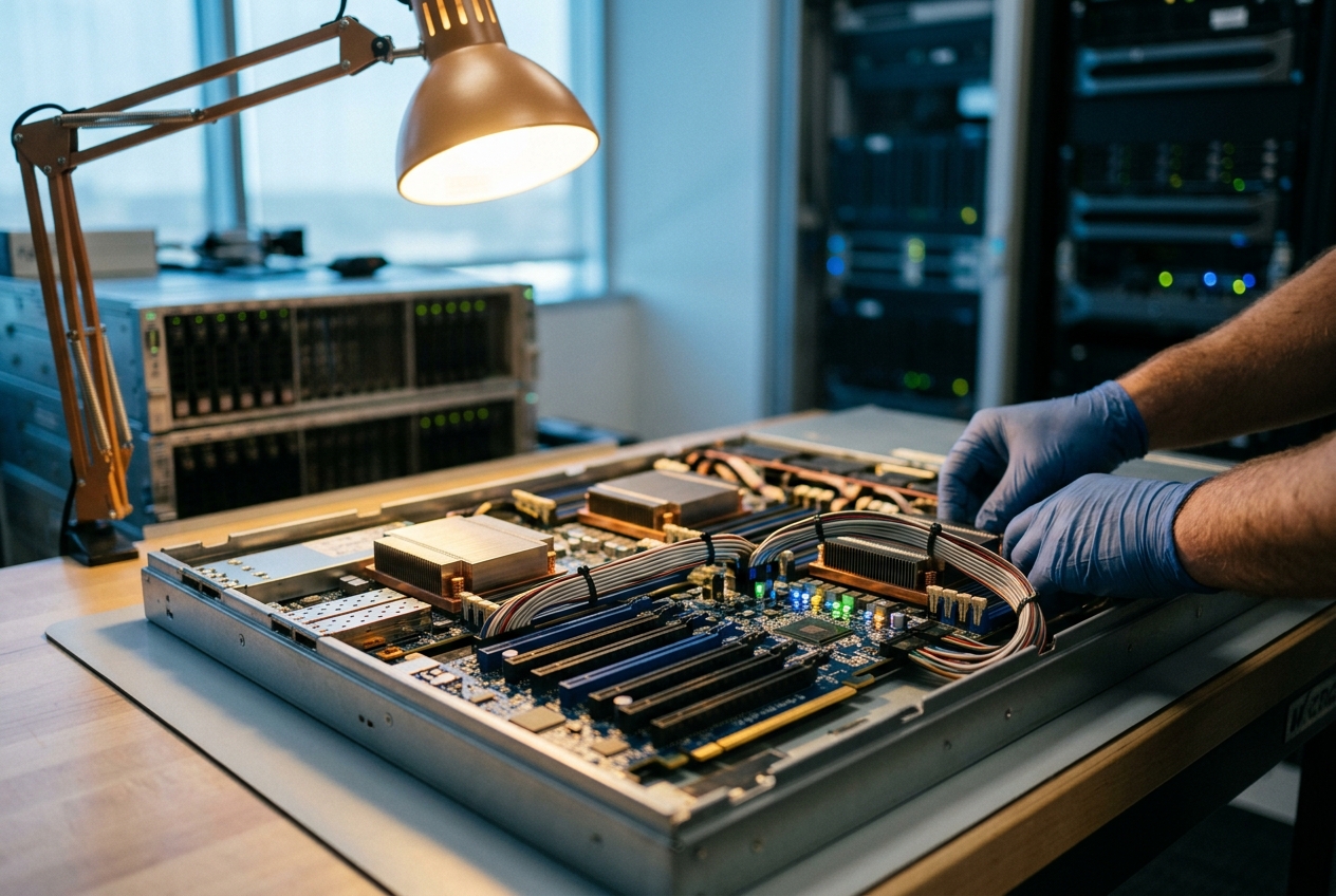
When software, memory, and storage drives all claim to be perfectly healthy yet a server grinds to a halt, the problem almost invariably lies in the physical conversations happening across the motherboard. Deep beneath the heat sinks and cooling fans, high-speed electronic lanes connect expansion cards to the central processor. When those physical channels suffer signaling faults or misconfigurations, standard application monitoring tools remain completely blind—leaving engineers chasing ghosts in software logs.
This is where lspci earns its place as an indispensable diagnostic tool. Short for "list PCI", it serves as an x-ray machine for a computer's internal hardware architecture. Rather than treating a server as an opaque black box, lspci peers into every graphics accelerator, network interface card, storage controller, and motherboard bridge plugged into the system, revealing precisely how physical components talk to the operating system and whether they are operating at their intended speeds.
To get your bearings during an outage, the most effective first step is to run a high-fidelity inventory that pairs plain-English hardware descriptions with the exact manufacturer identifiers:
lspci -nn
00:00.0 Host bridge [0600]: Intel Corporation Xeon E7 v4/Xeon E5 v4/Core i7 DMI2 [8086:6f00] (rev 01)
00:01.0 PCI bridge [0604]: Intel Corporation Xeon E7 v4/Xeon E5 v4/Core i7 PCI Express Root Port 1 [8086:6f02] (rev 01)
00:02.0 PCI bridge [0604]: Intel Corporation Xeon E7 v4/Xeon E5 v4/Core i7 PCI Express Root Port 2 [8086:6f04] (rev 01)
01:00.0 Non-Volatile memory controller [0108]: Samsung Electronics Co Ltd NVMe SSD Controller PM9A1/980PRO [144d:a80a]
02:00.0 Ethernet controller [0200]: Broadcom Inc. and subsidiaries NetXtreme BCM5720 Gigabit Ethernet PCIe [14e4:165f]
02:00.1 Ethernet controller [0200]: Broadcom Inc. and subsidiaries NetXtreme BCM5720 Gigabit Ethernet PCIe [14e4:165f]
03:00.0 3D controller [0302]: NVIDIA Corporation GA100 [A100 PCIe 80GB] [10de:20f5] (rev a1)
In a single glance, this command lays out every expansion card on the bus, showing its physical slot, functional class, vendor, model, and the hexadecimal device IDs needed for low-level system configuration.
How Hardware Communicates: Root Complexes, Configuration Spaces, and Sysfs
To understand what lspci is reporting, it helps to understand how modern computers connect their components. Modern motherboards no longer rely on the slow, shared parallel wiring of legacy PCI buses. Instead, PCI Express (PCIe) operates as a high-speed, packet-switched network of dedicated serial connections, governed by the international PCI-SIG Specifications.
Host-to-PCIe Bridge / ECAM & MMIO"] RC --> RP1["Root Port 00:01.0"] RC --> RP2["Root Port 00:02.0"] RC --> RP3["Root Port 00:03.0"] RP1 --> NVMe["NVMe Endpoint
(01:00.0)"] RP2 --> Switch["PCIe Switch Upstream Port
(02:00.0)"] RP3 --> NIC["100GbE NIC
(04:00.0)"] Switch --> DP1["Downstream Port"] Switch --> DP2["Downstream Port"] DP1 --> GPU["GPU Accelerator
(03:00.0)"] DP2 --> FPGA["FPGA Accelerator
(03:01.0)"]
The PCIe Hierarchy and Bus Addressing
At the top of this hardware pyramid sits the Root Complex, a dedicated controller built directly into the processor silicon that bridges the CPU's internal memory channels to the PCIe expansion slots. Every device plugged into this hierarchy receives a unique address using the Domain:Bus:Device.Function (DBDF) format:
- Domain: A 16-bit identifier (usually
0000) that isolates separate PCIe trees on multi-socket enterprise servers. - Bus: An 8-bit number (from
00toff) representing a distinct logical bus branch. - Device: A 5-bit slot identifier (from
00to1f) indicating a physical package on that bus. - Function: A 3-bit sub-device number (from
0to7), allowing a single expansion card—such as a dual-port network adapter—to present multiple independent interfaces to the operating system.
Configuration Spaces and Hardware Registers
Every PCIe device contains a dedicated 4,096-byte memory structure called the Configuration Space. When a computer boots, the motherboard and operating system inspect this memory space to discover what the hardware can do:
- Header Registers: The first 64 bytes describe whether the device is an endpoint (like a graphics card or NVMe SSD) or a bridge/switch. This header contains Vendor IDs, Device IDs, and Base Address Registers (BARs) that tell the CPU which system memory addresses are mapped to the device.
- Standard Capabilities: Starting at register offset
0x34, a linked list reveals standard features such as Power Management and Message Signaled Interrupts (MSI-X). - Extended Capabilities: Positioned above byte offset
0x100, this advanced list exposes enterprise capabilities such as Advanced Error Reporting (AER) and Single Root I/O Virtualization (SR-IOV).
The Linux Kernel Abstraction Layer
When Linux starts up, it probes the entire hardware tree and exposes its findings via the virtual filesystem documented in the Linux Kernel Sysfs Subsystem Guide. When you run lspci, the utility does not perform dangerous direct hardware reads; instead, it reads the structured data inside /sys/bus/pci/devices/. It translates raw hexadecimal numbers into readable descriptions by cross-referencing them against the community database described in the ArchWiki PCI Knowledgebase.
Essential Flags and Command-Line Navigation
The behavior of lspci is controlled through a series of modular flags. The table below outlines the core options used in production environments:
| Flag | Long Option | Purpose |
|---|---|---|
-v, -vv, -vvv |
--verbose |
Increases diagnostic detail exponentially, showing link speeds, memory BARs, and power states. |
-t |
--tree |
Renders a visual tree showing how buses, switches, and cards physically connect together. |
-k |
--kernel |
Displays the kernel driver currently controlling each device and lists available alternative modules. |
-s [[[[<domain>]:]<bus>]:][<slot>][.[<func>]] |
--slot |
Restricts output to a specific device slot using standard DBDF coordinates. |
-d [<vendor>]:[<device>][:<class>] |
--device |
Filters devices by manufacturer, model, or hardware class code. |
-n, -nn |
--numeric |
Displays numeric hex IDs (-n) or combines text names with numeric IDs (-nn). |
-D |
--domain |
Always prints the full PCI domain prefix (0000:), preventing ambiguity on large multi-socket servers. |
-mm, -M |
--machine |
Produces clean, tab-delimited key-value output designed for automated parsing in shell scripts. |
5 Real-World Production Scenarios
Scenario 1: Auditing Bus Topology to Resolve Hidden Bottlenecks
The Problem
A dual-socket database server experiences erratic latency spikes during heavy workloads. The machine contains four high-speed NVMe storage arrays and four 100GbE network cards. While network traffic and storage writes perform well in isolation, running both simultaneously cuts total throughput in half. The system administrator suspects that high-bandwidth cards have been plugged into slots that share a single internal PCIe switch, causing severe traffic congestion.
Buses 00-7f"] --> RP0["Root Port 00:01.0"] RP0 --> Switch0["PCIe Switch 01:00.0"] Switch0 --> NVMe0["NVMe Array [02:01.0]"] Switch0 --> NIC0["100GbE NIC [02:02.0]"] end subgraph Node1["NUMA Node 1 (Socket 1)"] CPU1["CPU 1 & Local Memory
Buses 80-ff"] --> RP1["Root Port 80:01.0"] RP1 --> NIC1["Mellanox ConnectX-6 [81:00.0]"] end
Production Command
To visualize the entire motherboard layout and see which devices share common switches and CPU sockets, run:
lspci -tv -nn
Realistic Terminal Output
-[0000:00]-+-00.0  Intel Corporation Xeon E7 v4/Xeon E5 v4/Core i7 DMI2 [8086:6f00]
           +-01.0-[01-02]----00.0-[02]--+-01.0  Samsung Electronics Co Ltd NVMe SSD Controller PM9A1/980PRO [144d:a80a]
           |                            \-02.0  Mellanox Technologies MT2892 Family [ConnectX-6 Dx] [15b3:101d]
           +-02.0-[03]----00.0  NVIDIA Corporation GA100 [A100 PCIe 80GB] [10de:20f5]
           \-03.0-[04]----00.0  Mellanox Technologies MT2892 Family [ConnectX-6 Dx] [15b3:101d]
-[0000:80]-+-01.0-[81]----00.0  Samsung Electronics Co Ltd NVMe SSD Controller PM9A1/980PRO [144d:a80a]
           \-02.0-[82]----00.0  Samsung Electronics Co Ltd NVMe SSD Controller PM9A1/980PRO [144d:a80a]
Detailed Line-by-Line Breakdown
-[0000:00]-and-[0000:80]-: These represent the two independent processor sockets (NUMA Node 0 managing buses00to7f, and NUMA Node 1 managing buses80toff).+-01.0-[01-02]----00.0-[02]--+: Root Port00:01.0connects to an unmanaged internal PCIe switch at01:00.0.\-01.0 ... [144d:a80a]and\-02.0 ... [15b3:101d]: The root cause. A high-throughput Samsung NVMe SSD (02:01.0) and a 100GbE Mellanox network card (02:02.0) are wired into the exact same switch, forcing them to compete for the same upstream bandwidth.-[0000:80]-...: Socket 1 hosts two NVMe drives on dedicated ports (81:00.0and82:00.0) with no network card present, confirming an unbalanced hardware configuration.
What the Administrator Does Next
The administrator schedules maintenance, powers down the server, and physically moves the Mellanox network card from slot 02:02.0 over to an empty slot wired directly to Socket 1 (0000:80). This eliminates the switch bottleneck and balances I/O traffic evenly across both processors.
Scenario 2: Detecting Silent PCIe Link Degradation on Accelerators
The Problem
An artificial intelligence cluster running model training jobs reports that one node is completing gradient synchronization 45% slower than identical sister nodes. The node houses an enterprise GPU designed to operate on a 16-lane PCIe Generation 4 connection (PCIe Gen4 x16, delivering ~31.5 GB/s of bandwidth). The administrator suspects that dust, slot misalignment, or thermal stress caused the card's electronic link to quietly down-negotiate to a slower speed.
Production Command
Inspect the target GPU's physical link capabilities and current operational status using maximum verbosity:
sudo lspci -vvv -s 0000:03:00.0
Realistic Terminal Output
03:00.0 3D controller: NVIDIA Corporation GA100 [A100 PCIe 80GB] (rev a1)
    Subsystem: NVIDIA Corporation GA100 [A100 PCIe 80GB]
    Physical Slot: 2
    Control: I/O- Mem+ BusMaster+ SpecCycle- MemWINV- VGASnoop- ParErr+ Stepping- SERR+ FastB2B- DisINTx+
    Status: Cap+ 66MHz- UDF- FastB2B- ParErr- DEVSEL=fast >TAbort- <TAbort- <MAbort- >SERR- <PERR- INTx-
    Latency: 0
    Interrupt: pin A routed to IRQ 48
    Region 0: Memory at 90000000 (32-bit, non-prefetchable) [size=16M]
    Region 1: Memory at 27800000000 (64-bit, prefetchable) [size=64G]
    Capabilities: [68] MSI: Enable+ Count=1/1 Maskable- 64bit+
    Capabilities: [78] Power Management version 3
    Capabilities: [88] Express (v2) Endpoint, MSI 00
        DevCap: MaxPayload 512 bytes, PhantFunc 0, ExtTag+
        DevCtl: CorrErr+ NonFatalErr+ FatalErr+ UnsupReq+
            MaxPayload 256 bytes, MaxReadReq 4096 bytes
        LnkCap: Port #0, Speed 16GT/s, Width x16, ASPM not supported
            ClockPM- Surprise- LLActRep- BwNot- ASPMOptComp+
        LnkCtl: ASPM Disabled; RCB 64 bytes, Disabled- CommClk+
            ExtSynch- ClockIntPrs- AutWidDis- BWInt- AutBWInt-
        LnkSta: Speed 8GT/s (downgraded), Width x4 (downgraded)
            TrErr- Train- SlotClk+ DLActive- BWMgmt- ABWMgmt-
Detailed Line-by-Line Breakdown
Capabilities: [88] Express (v2) Endpoint: Marks the official PCI Express Capability block at register offset0x88.LnkCap: Port #0, Speed 16GT/s, Width x16: The Hardware Specification. The silicon is rated for PCIe Generation 4 speeds (16 GigaTransfers/sec) across 16 physical lanes (Width x16).LnkSta: Speed 8GT/s (downgraded), Width x4 (downgraded): The Fault. The hardware failed to establish a clean Gen4 signal and down-trained to Gen3 speeds (8 GT/s) across only 4 lanes (x4). Effective transfer bandwidth has collapsed from 31.5 GB/s down to roughly 3.9 GB/s.TrErr- Train-: Confirms the link has stopped retraining and will remain trapped in this degraded state until physically reset.
What the Administrator Does Next
The administrator removes the server from the live cluster, shuts it down, extracts the GPU riser assembly, cleans the gold edge connectors with isopropyl alcohol to remove dust, and reseats the card firmly into the mechanical slot before rebooting.
Scenario 3: Debugging Virtual Machine Hardware Passthrough (VFIO)
The Problem
A systems engineer is configuring a virtualization host running Kernel-based Virtual Machines (KVM). The goal is to pass a physical GPU directly into a guest virtual machine using the VFIO Driver Architecture. However, launching the virtual machine fails immediately with an error: Device or resource busy. The engineer needs to confirm which driver has grabbed the card on the host.
(NVIDIA A100 GPU)"] Dev -.->|Incorrect Binding| Nouveau["nouveau Driver
(Host locks device; VM fails)"] Dev ==>|Target Binding| VFIO["vfio-pci Driver
(Device isolated for VM passthrough)"] end
Production Command
Check the device's driver status and examine available kernel modules:
lspci -nnk -s 0000:03:00.0
Realistic Terminal Output
03:00.0 3D controller [0302]: NVIDIA Corporation GA100 [A100 PCIe 80GB] [10de:20f5] (rev a1)
    Subsystem: NVIDIA Corporation GA100 [A100 PCIe 80GB] [10de:1463]
    Kernel driver in use: nouveau
    Kernel modules: nouveau, nvidia_drm, nvidia, vfio_pci
Detailed Line-by-Line Breakdown
03:00.0 3D controller [0302]: ... [10de:20f5]: Identifies the device class (0302for 3D controller), vendor ID (10defor NVIDIA), and product ID (20f5for A100).Kernel driver in use: nouveau: The Problem. The host operating system's default open-source graphics driver (nouveau) claimed the GPU during boot, preventing virtualization tools from accessing it.Kernel modules: nouveau, nvidia_drm, nvidia, vfio_pci: Lists all compiled drivers capable of controlling this card, confirming that the requiredvfio_pcimodule is present in the kernel.
What the Administrator Does Next
The administrator dynamically unbinds the GPU from nouveau and attaches it to vfio-pci using sysfs:
# Unbind the GPU from the host graphics driver
echo "0000:03:00.0" | sudo tee /sys/bus/pci/devices/0000:03:00.0/driver/unbind

# Bind the GPU to the VFIO passthrough driver
echo "vfio-pci" | sudo tee /sys/bus/pci/devices/0000:03:00.0/driver_override
echo "10de 20f5" | sudo tee /sys/bus/pci/drivers/vfio-pci/new_id
To make this change permanent across reboots, the administrator adds options vfio-pci ids=10de:20f5 to /etc/modprobe.d/vfio.conf.
Scenario 4: Validating SR-IOV Virtual Functions on Network Adapters
The Problem
A telecommunications platform uses Single Root I/O Virtualization (SR-IOV) to partition a physical 100GbE network card into multiple virtual network interfaces for containerized workloads. The deployment tool reports that it configured 8 virtual interfaces on physical port 0, but no new interfaces appear in the operating system. The administrator needs to verify whether SR-IOV is enabled in the card's firmware and active in the kernel.
Production Command
Inspect the network controller's extended capability blocks with full verbosity:
sudo lspci -vvv -s 0000:04:00.0
Realistic Terminal Output
04:00.0 Ethernet controller: Mellanox Technologies MT2892 Family [ConnectX-6 Dx]
    Subsystem: Mellanox Technologies MT2892 Family [ConnectX-6 Dx]
    Capabilities: [60] Express (v2) Endpoint, MSI 00
    Capabilities: [9c] MSI-X: Enable+ Count=64 Masked-
    Capabilities: [100 v1] Advanced Error Reporting
    Capabilities: [180 v1] Alternative Routing-ID Interpretation (ARI)
    Capabilities: [1c0 v1] Single Root I/O Virtualization (SR-IOV)
        IOVCap: Migration-, Interrupt-
        IOVCtl: Enable- Migration- Interrupt- MSE- ARIEn+
        IOVSta: Migration-
        InitialVFs: 8, TotalVFs: 8, NumberOfVFs: 0, FunctionDependencyLink: 00
        VF DeviceID: 101e
        VF migration: offset 00000000, BIR 0
        VF BAR 0: [prefetchable] Memory at 0000027810000000 [size=32M]
        VF BAR 2: [prefetchable] Memory at 0000027812000000 [size=32M]
Detailed Line-by-Line Breakdown
Capabilities: [1c0 v1] Single Root I/O Virtualization (SR-IOV): Confirms that the physical network adapter supports hardware-level virtualization.IOVCtl: Enable- ... MSE-: The Blocker. The SR-IOV control register indicates that Virtual Functions are currently disabled (Enable-) and memory mapping is inactive (MSE-).InitialVFs: 8, TotalVFs: 8, NumberOfVFs: 0: The silicon supports up to 8 virtual functions (TotalVFs: 8), but exactly zero are currently allocated (NumberOfVFs: 0).VF DeviceID: 101e: Indicates that once instantiated, virtual functions will appear on the bus with device ID15b3:101e.
What the Administrator Does Next
The administrator instructs the kernel to instantiate the 8 virtual functions by writing directly to the sysfs configuration node:
echo 8 | sudo tee /sys/bus/pci/devices/0000:04:00.0/sriov_numvfs
Running lspci again confirms IOVCtl: Enable+ MSE+ and shows eight new virtual network adapters (0000:04:00.1 through 0000:04:01.0) ready for container assignment.
Scenario 5: Fleet-Wide Hardware Auditing and Error Telemetry
The Problem
In a large fleet of bare-metal servers, physical PCIe connection errors—such as bad transaction layer packets or electrical receiver faults—often occur silently for days before causing an outright kernel panic. The reliability team needs an automated script to audit thousands of nodes, extract clean hardware inventories, and flag any machine showing early signs of physical link corruption.
Telemetry Recorded"] Parse -->|Errors Flagged: BadTLP+, RxErr+| Flagged["AER Anomaly Alert Triggered"] Flagged --> Drain["Trigger Automated Node Drain & RMA Replacement"]
Production Command
Generate clean, tab-delimited records suitable for automated parsing:
sudo lspci -D -mm -nn
Realistic Terminal Output
Slot:   0000:00:00.0
Class:  Host bridge [0600]
Vendor: Intel Corporation [8086]
Device: Xeon E7 v4/Xeon E5 v4/Core i7 DMI2 [6f00]
SVendor:    Intel Corporation [8086]
SDevice:    Device [0000]
Rev:    01

Slot:   0000:01:00.0
Class:  Non-Volatile memory controller [0108]
Vendor: Samsung Electronics Co Ltd [144d]
Device: NVMe SSD Controller PM9A1/980PRO [a80a]
SVendor:    Samsung Electronics Co Ltd [144d]
SDevice:    Device [a801]

Slot:   0000:03:00.0
Class:  3D controller [0302]
Vendor: NVIDIA Corporation [10de]
Device: GA100 [A100 PCIe 80GB] [20f5]
SVendor:    NVIDIA Corporation [10de]
SDevice:    GA100 [A100 PCIe 80GB] [1463]
Rev:    a1
Automated Shell Telemetry Parser
To inspect Advanced Error Reporting (AER) registers across all devices and catch failing hardware before a crash occurs, the team deploys this automated script:
#!/usr/bin/env bash
set -euo pipefail

echo "=== INITIATING FLEET-WIDE AER INTEGRITY AUDIT ==="

# Iterate through every PCI device registered in sysfs
for dev in /sys/bus/pci/devices/*; do
    dbdf=$(basename "${dev}")

    # Check whether the device exposes Advanced Error Reporting registers
    aer_output=$(sudo lspci -vvv -s "${dbdf}" 2>/dev/null | awk '/Advanced Error Reporting/,/^$/' || true)

    if [[ -n "${aer_output}" ]]; then
        # Check for uncorrectable (UESta) or correctable (CESta) error flags
        if echo "${aer_output}" | grep -E "(UESta.*[A-Za-z]\+|CESta.*[A-Za-z]\+)" | grep -vq "None"; then
            echo "[ALERT] Hardware Degradation Detected on ${dbdf}"
            echo "--- AER Diagnostics for ${dbdf} ---"
            echo "${aer_output}" | grep -E "(UESta|CESta|DevSta|LnkSta)"
            echo "-------------------------------------"
        fi
    fi
done

echo "=== AUDIT COMPLETE ==="
Detailed Breakdown
-D: Forces inclusion of the full domain prefix (0000:), preventing naming collisions on multi-socket servers.-mm: Outputs structured key-value pairs separated by tabs, ensuring scripts will not break if upstream tools change display formatting.- The script inspects the
UESta(Uncorrectable Error Status) andCESta(Correctable Error Status) registers defined in the official Linux Kernel PCI Documentation. Bits marked with a plus sign (such asBadTLP+orRxErr+) flag electrical degradation before it causes catastrophic data loss.
What the Administrator Does Next
When the automated script detects accumulating error flags on a server, the fleet management system automatically cordons the node, evacuates its workloads to healthy machines, and opens a hardware ticket to replace the failing card.
Common Pitfalls and Operational Gotchas
1. The Missing Privileges Trap
Running lspci without administrative privileges (sudo) silently hides critical diagnostic registers. To protect physical memory offsets from unauthorized inspection, the Linux kernel restricts unprivileged access to parts of the underlying sysfs files.
* The Pitfall: Advanced Error Reporting (AER) logs, serial numbers, and link training details will simply be missing from output without any error message.
* The Fix: Always run sudo lspci -vvv when diagnosing hardware issues.
2. Parsing Plain Text in Scripts
A common mistake in shell automation is using tools like awk or cut on standard lspci text output based on visual column positions.
* The Pitfall: Device names and descriptions vary significantly across Linux distributions and package updates, causing text-scraping scripts to fail unexpectedly.
* The Fix: Always use lspci -D -mm -nn or read directly from the stable files in /sys/bus/pci/devices/.
3. Outdated Device Databases
Running lspci on newly released enterprise hardware can produce generic, unhelpful labels like Unassigned class [ff00] or Device [10de:2235].
* The Pitfall: Hardware may appear unconfigured or broken simply because the local name translation file is out of date.
* The Fix: Update your local hardware database against the global registry with a single command:
bash
  sudo update-pciids
Today's Takeaway
Open a terminal on your Linux machine and run sudo lspci -vvv | grep -E "(LnkCap|LnkSta)" -B 2. In less than five seconds, this single pipeline will compare every expansion card's maximum rated design speed against its actual negotiated link speed, instantly highlighting any loose cards, dirty slots, or degraded PCIe lanes hidden inside your system.